True/False
Indicate whether the
statement is true or false.
|
|
|
1.
|
The best method of designing a motor control circuit is to solve one requirement
at a time.
|
|
|
Figure 41-3 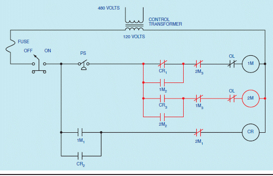
|
|
|
2.
|
In the accompanying figure, each motor starter coil is protected by a separate
overload contact.
|
|
|
Figure 41-7 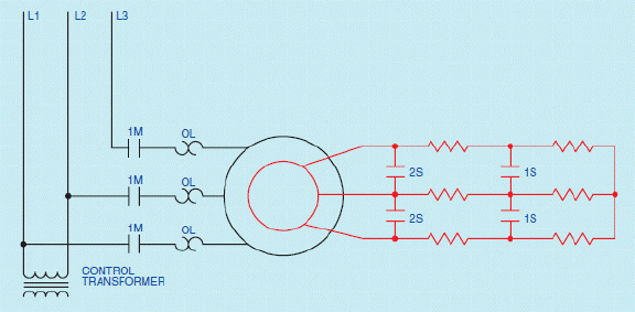
|
|
|
3.
|
In the accompanying figure, speed control for a wound rotor motor is obtained by
placing resistance in the secondary or rotor circuit.
|
|
|
Figure 41-08 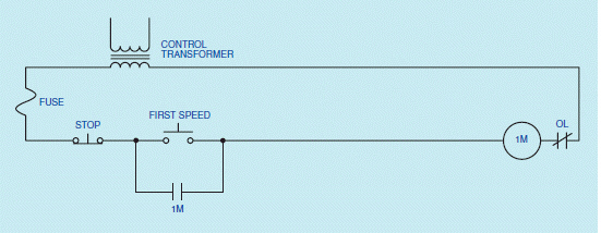
|
|
|
4.
|
In the accompanying diagram, when the FIRST SPEED button is pressed, motor
starter coil 1M will close and connect the stator of the motor to the power line.
|
|
|
5.
|
In the accompanying figure, auxiliary contact 1M cannot be used as a holding
contact.
|
Completion
Complete each
statement.
|
|
|
Figure 41-1 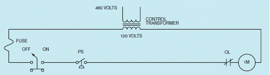
|
|
|
6.
|
In the accompanying figure, a(n) ____________________ is used as short-circuit
protection for the control wiring.
|
|
|
7.
|
In the accompanying figure, a(n) ____________________ has been used to step down
the 480-volt supply line voltage to 120 volts for use by the control circuit.
|
|
|
Figure 41-02 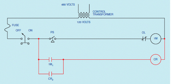
|
|
|
8.
|
In the accompanying figure, because control relay CR is used as a(n)
____________________, it must be permitted to remain energized when either or both of the motor
starters are not energized.
|
|
|
Figure 41-5 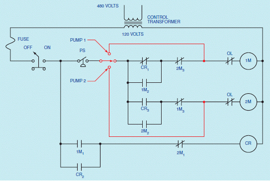
|
|
|
9.
|
In the accompanying figure, a(n) ____________________ switch is connected to the
output of the pressure switch.
|
|
|
Figure 41-7
|
|
|
10.
|
In the accompanying figure, second speed is obtained by closing
____________________ and shorting out the first three phase resistor bank.
|
Short Answer
|
|
|
Figure 41-1
|
|
|
11.
|
In the accompanying figure, why must the pressure switch be connected as
normally closed?
|
|
|
Figure 41-4 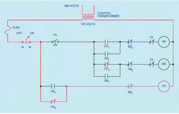
|
|
|
12.
|
In the accompanying figure, what happens when the pressure switch opens?
|
|
|
Figure 41-5
|
|
|
13.
|
In the accompanying figure, what does the selector switch permit?
|
|
|
Figure 41-7
|
|
|
14.
|
In the accompanying figure, what is the function of load contacts 1M?
|
|
|
15.
|
In the accompanying figure, what happens when power is applied to the
stator?
|