Multiple Choice
Identify the
choice that best completes the statement or answers the question.
|
|
|
1.
|
The body of a single-acting, spring-return cylinder has ______________.
a. | one connection port | c. | no connection ports | b. | two connection ports | d. | four connection
ports |
|
|
|
2.
|
The 3-way DCV is used in applications where the actuator needs to be powered in
___________.
a. | one direction | c. | three directions | b. | two directions | d. | four directions |
|
|
|
3.
|
The 3-way DCV is held in the energized position by the _____________.
a. | operator | c. | body | b. | spool | d. | spring |
|
|
|
4.
|
Which pneumatic actuator converts compressed air flow into mechanical
power?
a. | Motor | c. | double acting cylinder | b. | Single acting
cylinder | d. | All of the
above |
|
|
|
5.
|
Pneumatic motors operate by using air pressure to create a turning force called
__________.
a. | rotation | c. | torque | b. | back pressure | d. | uni-directional |
|
|
|
6.
|
To reduce the noise of a pneumatic 3-position, 4-way DCV, a ____________ is
used.
a. | spring | c. | spool | b. | quick-connection fitting | d. | muffler |
|
|
|
7.
|
Two of the most common design types of pneumatic motors are
_______________.
a. | turbine and piston | c. | van and V-type | b. | lobed rotor and vane | d. | vane and piston |
|
|
|
8.
|
Symbols in pneumatics are used to show ________________.
a. | size of components | c. | port locations | b. | function | d. | pressure
settings |
|
|
|
9.
|
The single-acting spring return cylinder is extended by the
_________________.
a. | load | c. | spring | b. | pressure | d. | bushing |
|
|
|
10.
|
A dashed line in a pneumatic schematic diagram represents a(n)
_____________.
a. | main line | c. | pilot line | b. | exhaust line | d. | enclosure line |
|
Matching
|
|
|
Segment 1
a. | load | d. | spool | b. | three | e. | spring-return | c. | 3-way |
|
|
|
11.
|
The pneumatic 3-way DCV has _______ ports.
|
|
|
12.
|
The part of the 3-way DCV that changes the flow path is called the
_________.
|
|
|
13.
|
A single-acting _________ cylinder consists of a piston/rod assembly, a single
port, and a spring.
|
|
|
14.
|
Single-acting cylinders are returned by springs or the ________.
|
|
|
15.
|
A(n) ________ DCV is used when an actuator needs to be powered in one direction
only.
|
|
|
Segment 2
a. | axial | d. | vanes | b. | rotary | e. | vane | c. | uni-directional | f. | mufflers |
|
|
|
16.
|
The pneumatic motor converts fluid power to _______ motion.
|
|
|
17.
|
To reduce the noise level from air motors, _________ are used in the
exhaust.
|
|
|
18.
|
The _________ piston air motor has a high starting torque.
|
|
|
19.
|
The three most commonly available pneumatic motors are the axial piston, radial
piston, and __________.
|
|
|
20.
|
Motors which are designed to operate in only one direction are called
______________.
|
|
|
21.
|
Smoother rotation is obtained from a vane type motor with more
__________.
|
|
|
Segment 3
a. | air | d. | pilot | b. | rotated | e. | electric drive motor | c. | exhaust or
drain |
|
|
|
22.
|
A dotted line represents a(n) _____________, when using pneumatic
schematics.
|
|
|
23.
|
The letter M inside of a circle indicates ____________.
|
|
|
24.
|
Dashed lines indicate a(n) ___________ line when using pneumatic
schematics.
|
|
|
25.
|
Symbols may be ________ or reversed without altering their function or
condition.
|
|
|
26.
|
A hollow arrow in a schematic indicates that the medium is __________.
|
|
|
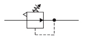
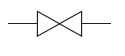
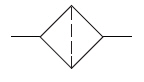
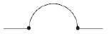
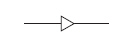
Identifying Pneumatic Symbols Part 1
a. | Hose | e. | Pressure Gauge | b. | Shutoff
Valve | f. | Blocked
Line | c. | Regulator | g. | Muffler | d. | Filter |
|
|
|
27.
|

|
|
|
28.
|
|
|
|
29.
|
|
|
|
30.
|
|
|
|
31.
|

|
|
|
32.
|
|
|
|
33.
|
|
|
|
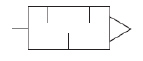
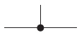
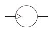
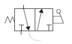
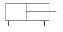
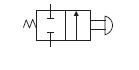
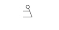
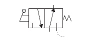
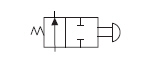
Identifying Pneumatic Symbols Part 2
a. | Tee | d. | 3-Way DCV N.C. | b. | Pilot
Line | e. | Double-Acting
Cylinder | c. | Unidirectional Pneumatic Motor | f. | Single-Acting
Cylinder |
|
|
|
34.
|
|
|
|
35.
|
|
|
|
36.
|
|
|
|
37.
|
|
|
|
38.
|
|
|
|
39.
|
|
|
|
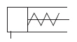
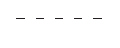
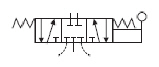
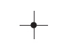
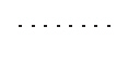
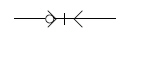
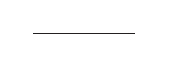
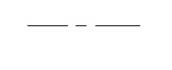
Identifying Pneumatic Symbols Part 3
a. | Exhaust Line | f. | 5/3 DCV Manually
Operated | b. | Lever Operator | g. | 3/2 DCV N.O. | c. | Main Conductor | h. | Cross | d. | Spring | i. | 2/2
DCV N.C. | e. | Quick Connect |
|
|
|
40.
|

|
|
|
41.
|
|
|
|
42.
|
|
|
|
43.
|
|
|
|
44.
|
|
|
|
45.
|
|
|
|
46.
|
|
|
|
47.
|
|
|
|
48.
|
|
|
|
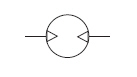
Identifying Pneumatic Symbols Part 3
a. | Enclosure Line | c. | Flow
Direction | b. | Bidirectional Pneumatic Motor | d. | 2-Way DCV N.O. |
|
|
|
49.
|
|
|
|
50.
|
|
|
|
51.
|
|
|
|
52.
|
|