True/False
Indicate whether the
statement is true or false.
|
|
|
1.
|
There are three principle types of shaft couplings, rigid, flexible, and
universal joints.
|
|
|
2.
|
Rigid shaft couplings are used when a fixed union is required to connect two
rotating shafts.
|
|
|
3.
|
Shock and intermittent transient loads can damage connected equipment unless
dampened.
|
|
|
4.
|
A single type Universal Joint will accommodate angular misalignment but not
parallel/offset misalignment.
|
Multiple Choice
Identify the
choice that best completes the statement or answers the question.
|
|
|
5.
|
This is a ___________. 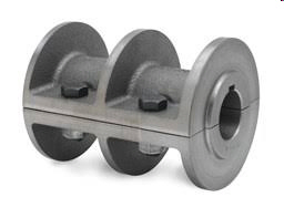 a. | Rigid Sleeve Coupling | c. | Ribbed Rigid Coupling | b. | Flanged Rigid
Coupling | d. | Flex
Coupling |
|
|
|
6.
|
This is a ___________. 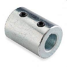 a. | Rigid Sleeve Coupling | c. | Ribbed Rigid Coupling | b. | Flanged Rigid
Coupling | d. | Flex
Coupling |
|
|
|
7.
|
This is a ___________. 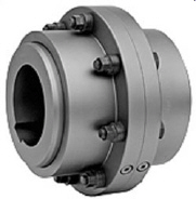 a. | Rigid Sleeve Coupling | c. | Ribbed Rigid Coupling | b. | Flanged Rigid
Coupling | d. | Flex
Coupling |
|
|
|
8.
|
This is a _____________. 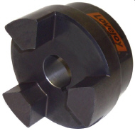 a. | Jaw Coupling Cushion | c. | Flexible Sleeve Coupling | b. | Jaw
Coupling | d. | Tire
Coupling |
|
|
|
9.
|
This is a _____________. 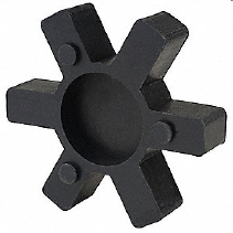 a. | Jaw Coupling Cushion | c. | Flexible Sleeve Coupling | b. | Jaw
Coupling | d. | Tire
Coupling |
|
|
|
10.
|
This is a _____________. 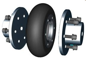 a. | Jaw Coupling Cushion | c. | Flexible Sleeve Coupling | b. | Jaw
Coupling | d. | Tire
Coupling |
|
|
|
11.
|
This is a _____________. 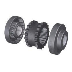 a. | Jaw Coupling Cushion | c. | Flexible Sleeve Coupling | b. | Jaw
Coupling | d. | Tire
Coupling |
|
|
|
12.
|
This is a _____________. 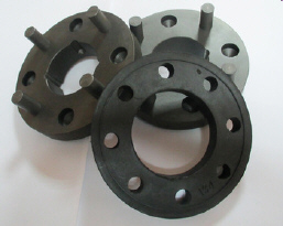 a. | Donut Coupling | c. | Pin and Disc Coupling | b. | Pin and Bushing
Coupling | d. | Elastomeric Sleeve
Gear Coupling |
|
|
|
13.
|
This is a _____________. 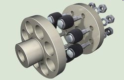 a. | Donut Coupling | c. | Pin and Disc Coupling | b. | Pin and Bushing
Coupling | d. | Elastomeric Sleeve
Gear Coupling |
|
|
|
14.
|
This is a _____________. 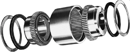 a. | Donut Coupling | c. | Pin and Disc Coupling | b. | Pin and Bushing
Coupling | d. | Elastomeric Sleeve
Gear Coupling |
|
|
|
15.
|
This is a _____________. 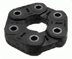 a. | Donut Coupling | c. | Pin and Disc Coupling | b. | Pin and Bushing
Coupling | d. | Elastomeric Sleeve
Gear Coupling |
|
|
|
16.
|
This is a _____________. 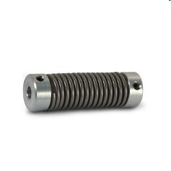 a. | Spring Coupling | c. | Beam Coupling | b. | Chain Coupling | d. | Fluid Coupling |
|
|
|
17.
|
This is a _____________. 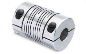 a. | Spring Coupling | c. | Beam Coupling | b. | Chain Coupling | d. | Fluid Coupling |
|
|
|
18.
|
This is a _____________. 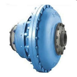 a. | Spring Coupling | c. | Beam Coupling | b. | Chain Coupling | d. | Fluid Coupling |
|
|
|
19.
|
This is a _____________. 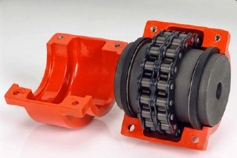 a. | Spring Coupling | c. | Beam Coupling | b. | Chain Coupling | d. | Fluid Coupling |
|
Completion
Complete each
statement.
|
|
|
20.
|
A shaft _________ is essentially a sleeve connecting two rotating shafts,
transmitting the torque from driver to driven machines.
|
|
|
21.
|
The rigid shaft coupling allows no _____________ between shafts and its use is
limited.
|
|
|
22.
|
The flexible shaft coupling sllows some _________ of the connected
shafts.
|
|
|
23.
|
Uinversal joints are used in connecting shafts that have extreme
______________.
|
|
|
24.
|
__________ shaft couplings are designed to flex under the various loads acting
on them.
|
|
|
25.
|
A _________ coupling has a spacer of different standardized lengths added into
the unit to bridge the gap between shaft ends.
|
|
|
26.
|
____________ stiffness is a resistance to twisting action between driving and
driven halves of coupling.
|
Matching
|
|
|
a. | Ribbed Rigid Couplings | c. | Flanged Rigid Couplings | b. | Rigid Sleeve
Couplings |
|
|
|
27.
|
Couplings that have halves that are split vertically and bolted
together.
|
|
|
28.
|
Couplings that have two horizontally split halves bolted together.
|
|
|
29.
|
A steel sleeve machined from a single bar, with a hole drilled in it.
|
|
|
a. | Spring Coupling | g. | Beam Coupling | b. | Fluid Coupling | h. | Pin and Bushing Coupling | c. | Pin and Disc
Coupling | i. | Gear
Coupling | d. | Donut Coupling | j. | Single Universal Joint Coupling | e. | Chain Coupling | k. | Tire Coupling | f. | Jaw
Coupling | l. | Elastomeric Sleave
Gear Coupling |
|
|
|
30.
|
Accomodates angular misalignment but not parallel/offset misalignment.
|
|
|
31.
|
A two piece apparatus consisting of an impeller and a runner contained within a
casing.
|
|
|
32.
|
Couplings that have limited misalignment capacity and low shock and vibration
dampening capability.
|
|
|
33.
|
It is sometimes refered to as the “constant velocity”
coupling.
|
|
|
34.
|
Small couplings that handle limited amounts of torque, but speeds as high as
30,000 rpm with smaller units.
|
|
|
35.
|
Couplings that are “power dense” and will handle very high amounts
of torque and horsepower.
|
|
|
36.
|
Couplings primarily used on light duty industrial applications such as the
input shaft of a fractional horsepower motor reducer.
|
|
|
37.
|
Couplings that have two hubs and a single solid flexible element.
|
|
|
38.
|
This coupling has a high capacities for misalignment. The bushings can be
made from rubber compounds, urethane or neoprene.
|
|
|
39.
|
These couplings can handle cycle loads and dampen vibration that passes through
the coupling.
|
|
|
40.
|
Couplings that accommodate significant amounts of both angular misalignment (up
to 4 degrees) and parallel/offset (up to 1/8”)
|
|
|
41.
|
One of the most common forms of nonmetallic couplings that require the use of
inserts or spiders.
|
|
|
a. | Rim/Face Alignment Method | c. | Straight Edge/Feeler Gauge/Taper
Guage Allignment Method | b. | Straight Edge Allignment
Method | d. | Single Dial
Indicator Method |
|
|
|
42.
|
Makes the alignment process less time-consuming than more sophisticated
methods.
|
|
|
43.
|
Offset and angular gaps are measured using two dial indicators.
|
|
|
44.
|
It has the advantage of being used when only one shaft can be rotated.
|
|
|
45.
|
The simplest and oldest type of alignment procedure.
|