True/False
Indicate whether the
statement is true or false.
|
|
|
1.
|
If two resistors are in
parallel, they drop the same voltage.
|
|
|
2.
|
A series-parallel circuit consists of resistors in both
series and parallel.
|
|
|
3.
|
No problems could occur if a 10
V source and a 20 V source were connected in parallel.
|
|
|
4.
|
A loaded voltage divider is a
series-parallel
circuit.
|
|
|
5.
|
Two or more resistors connected
in series form a circuit known as a voltage divider.
|
|
|
6.
|
A voltmeter, when connected
across a component, can be viewed as being a resistor in series with that
component.
|
|
|
7.
|
Thevinizing a circuit creates
an equivalent series circuit.
|
|
|
8.
|
Maximum power is achieved when
the load resistance is approximately two times the source resistance.
|
|
|
9.
|
R2 is in parallel with R3 in
Figure 6-1.

Figure 6-1
|
|
|
10.
|
R1 is in series with R3 in
Figure 6-1.
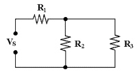
Figure 6-1
|
|
|
11.
|
R1 is in series with the
parallel combination R2 and R3 in Figure 6-1.
|
|
|
12.
|
R1 is in series with the series
combination R2 and R3 in Figure 6-1.
|
Multiple Choice
Identify the
choice that best completes the statement or answers the question.
|
|
|
13.
|
In Figure 6-1, R2 is connected
in ________.

Figure 6-1
a. | parallel with
R1 | c. | series with
R3 | b. | series with
R1 | d. | parallel with
R3 |
|
|
|
14.
|
In Figure 6-1, R1 is connected in ________.

Figure
6-1
a. | parallel with
R3 | b. | series with
R2 | c. | parallel with
R2 | d. | series with
R3 | e. | none of the
above |
|
|
|
15.
|
If R1 = 4.7 kÙ,
R2 = 3.3 kÙ and R3 = 1 kÙ in Figure
6-1, the total resistance equals ________.

Figure
6-1
a. | 5467 Ù | c. | 5700
Ù | b. | 660 Ù | d. | 4125
Ù |
|
|
|
16.
|
If R1 = 10 kÙ,
R2 = 15 kÙ and R3 = 50 kÙ in Figure
6-1, RT equals ________.

Figure
6-1
a. | 21.5 kÙ | c. | 9.5
kÙ | b. | 11.5 kÙ | d. | 10
kÙ |
|
|
|
17.
|
If Vs = 25 V, R1 = 10
kÙ, R2 = 15 kÙ and R3 = 50 kÙ in
Figure 6-1, IT equals ________.

Figure 6-1
a. | 2.5 mA | c. | 1.58 mA | b. | 1.16 mA | d. | 2.17 mA |
|
|
|
18.
|
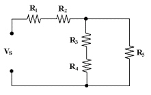
If all of the resistors in Figure 6-2 are 4.7
kÙ, what is the value of RT?

Figure 6-2
a. | 4.7 kÙ | c. | 9.4
kÙ | b. | 12.5 kÙ | d. | 18.8
kÙ |
|
|
|
19.
|
In Figure 6-2, R3 and R4 are
connected in ________.

Figure
6-2
a. | series with each other and
R5 | c. | series with each
other | b. | parallel with R1 and R2 | d. | series with each other and R1 and
R2 |
|
|
|
20.
|
If R1 = 50 kÙ,
R2 = 10 kÙ, R3 = 10 kÙ, R4 = 50 kÙ and R5 = 10 kÙ in Figure 6-2,
what is the value of RT?

Figure
6-2
a. | 8.57 kÙ | c. | 85.7
kÙ | b. | 68.6 kÙ | d. | 130
kÙ |
|
|
|
21.
|
If all resistors equal
4.7 kÙ and Vs equals 20 V in Figure 6-2, what is the value of
IR3?

Figure 6-2
a. | 11.99
mA | c. | 1.06
mA | b. | 12.5
mA | d. | 0.53 mA |
|
|
|
22.
|
In Figure 6-2, R3 and R4 are
connected in ________.
Figure
6-2
a. | series with each other and in
parallel with R5 | b. | series with R2 | c. | parallel with each other | d. | series with
R5 |
|
|
|
23.
|
If every resistor in Figure 6-2 equals 2.2 kÙ,
what is the value of RT?

Figure
6-2
a. | 5.5 kÙ | c. | 5.87
kÙ | b. | 2.2 kÙ | d. | 4.4
kÙ |
|
|
|
24.
|
In Figure 6-2 if R1 = 10
kÙ, R2 = 4.7 kÙ, R3 = 4.7 kÙ,
R4 = 10 kÙ and R5 = 4.7 kÙ, RT = ?

Figure
6-2
a. | 6.1 kÙ | c. | 0
Ù | b. | 24.7 kÙ | d. | 18.3
kÙ |
|
|
|
25.
|
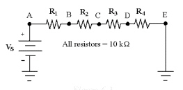
If VR4 = 10 V in Figure 6-3,
what is the value of VAD?

Figure
6-3
|
|
|
26.
|
What is the resistance between
points A and D in Figure 6-3?

Figure
6-3
a. | 30 kÙ | c. | 10
kÙ | b. | 40 kÙ | d. | 20
kÙ |
|
|
|
27.
|
If VR1 = 15 V in Figure 6-3,
what is the value of VBD?

Figure
6-3
a. | 30 V | c. | -60 V | b. | -30 V | d. | 60 V |
|
|
|
28.
|
If Vs = 50 V in Figure 6-3,
what is the value of VCA?

Figure
6-3
|
|
|
29.
|
If the current is 12 mA in
Figure 6-3, what is the value of VEB?
Figure
6-3
a. | -240 V | c. | 360 V | b. | 240 V | d. | -360 V |
|
|
|
30.
|
If the current is 1.2 mA in
Figure 6-3, what is the value of PT?

Figure
6-3
a. | 576 mW | c. | 0.576 mW | b. | 57.6 mW | d. | 5.76 mW |
|
|
|
31.
|
If VR3 = 17 V in Figure 6-3,
what is the value of P1?

Figure
6-3
a. | 1.7 mW | c. | 17 mW | b. | 2.89 W | d. | 28.9 mW |
|
|
|
32.
|
If four parallel 10 kÙ resistors are connected
in series with a single 20 kÙ resistor and one of the parallel resistors opens, how does the
voltage across the other parallel resistors change?
a. | It
decreases. | c. | It
increases. | b. | It remains the same. |
|
|
|
33.
|
Two series 1 kÙ resistors are connected in
parallel with a 2.2 kÙ resistor. If the voltage across one of the 1 kÙ resistors is 6 V,
what is the voltage across the 2.2 kÙ resistor?
|
|
|
34.
|
The parallel combination of a 330 Ù resistor
and a 470 Ù resistor is connected in series with the parallel combination of four 1 kÙ
resistors. If a 100 V source is connected across the circuit, then which resistor
carries the most current?
|
|
|
35.
|
The parallel combination of a 330 Ù resistor
and a 470 Ù resistor is connected in series with the parallel combination of four 1 kÙ
resistors. If a 100 V source is connected across the circuit, then which resistor drops the most
voltage?
|
|
|
36.
|
If a voltage divider consists of two 10 kÙ
resistors, which one of these load resistors will change the output voltage the
most?
a. | 100 kÙ | c. | 20
kÙ | b. | 1 MÙ | d. | 10
kÙ |
|
|
|
37.
|
In a two-source circuit, one
source alone produces 10 mA through a branch. If the other source alone produces 8 mA in the opposite
direction through the same branch, what is the total current through the branch?
a. | 18 mA | c. | 8 mA | b. | 10 mA | d. | 2 mA |
|
|
|
38.
|
If four parallel 10 kÙ resistors are in series
with a single 20 kÙ resistor and one of the parallel resistors shorts, the voltage across the
other parallel resistors ________.
a. | decreases | c. | remains the same | b. | increases |
|
|
|
39.
|
Power in a series-parallel
resistor circuit is dissipated as:
a. | current
flow. | c. | voltage
loss. | b. | heat. | d. | resistance
change. |
|
|
|
40.
|
In solving series-parallel
circuits using Ohm's law, first solve for:
a. | IT. | c. | RT. | b. | ET. | d. | any of these, it doesn't
matter. |
|
|
|
41.
|
In solving series-parallel
circuits using Ohm's law, first solve for:
a. | the series
current. | c. | the parallel
current. | b. | the parallel resistance. | d. | the series resistance. |
|
|
|
42.
|
In the series portion of
series-parallel circuits, the total resistance is:
a. | less than the largest
resistance. | c. | less than any one
resistance. | b. | greater than the largest resistance. | d. | equal to the largest resistance. |
|
|
|
43.
|
In the parallel portion of
series-parallel circuits, the total resistance is:
a. | equal to the smallest
resistance. | c. | less than the
smallest resistance. | b. | greater than the largest resistance. | d. | less than any one resistance. |
|
|
|
44.
|
Thevenin's theorem
provides a method for:
a. | simplifying complex series-parallel
circuits. | b. | designing complex series-parallel circuits. | c. | building complex series-parallel
circuits. | d. | all of these. |
|
|
|
45.
|
According to the maximum power
transfer theorem, maximum power is delivered to any load when the load resistance
is:
a. | at least twice or more than the
source resistance. | b. | less than one-half of the source resistance. | c. | larger than source
resistance. | d. | exactly equal to the source
resistance. |
|
|
|
46.
|
The super position theorem
provides a method for:
a. | analyzing complex series-parallel
circuits. | b. | building complex series-parallel circuits. | c. | designing complex series-parallel
circuits. | d. | all of these. |
|
|
|
47.
|
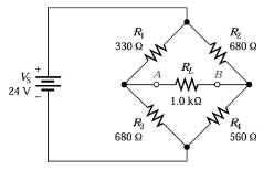
Refer to Figure 6-4. What approximate R1 resistor value
would it take to balance this bridge circuit?

Figure 6-4
a. | 825 Ù | c. | 330
Ù | b. | 560 Ù | d. | 680
Ù |
|
|
|
48.
|
Refer to Figure 6-4. With
circuit balanced there is:
Figure
6-4
a. | no current flow through the total
circuit. | b. | Cannot be determined without detailed
analysis. | c. | maximum current flow through the load. | d. | no current through the
load. |
|
|
|
49.
|
Refer to Figure 6-4. If
R1 is changed to 500 Ù, the Thevenin resistance and voltage would be:

Figure 6-4
a. | 595 and 807
mV. | c. | 1 k and 807
mV. | b. | 1 k and 3 V. | d. | 595 and 3 V. |
|
|
|
50.
|
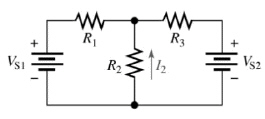
Refer to Figure 6-5. If all of the resistors of
this circuit are 5 kÙ and VS1 and VS2 are 10 V but opposing polarities, what
would be the current flow through R2?
Figure
6-5
a. | 2.66 mA | c. | 0 A | b. | 13.33 mA | d. | 1.33 mA |
|