Asynchronous counters can
be designed with small-scale and medium-scale integrated circuits. The small-scale design can utilize
virtually any flip-flop type. To observe this process, we will simulate and analyze multiple 3-bit
counters based on both D and J/K flip-flops.
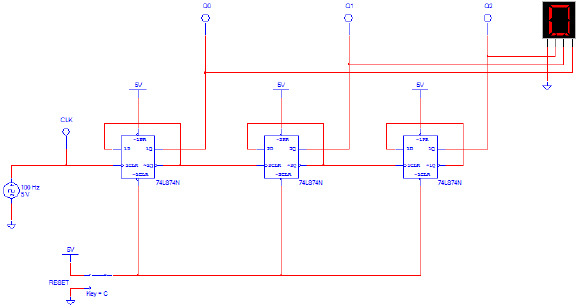
The circuit shown below is a 3-Bit Binary-Up Counter
implemented with 74LS74 D flip-flops. This design will count from 0 to 7 and then repeat. New to this
design is a HEX DISPLAY used to display the count. The HEX DISPLAY is similar to a seven-segment
display, but rather than having an input for each segment, it has only four. This device has a
built-in decoder that converts a binary number into its corresponding display digit. For example an
input of ‘0110’ would display a ‘6’, and a ‘1010’ would display
an ‘A’.
 3-Bit Binary-Up Counter with D
Flip-Flops
3-Bit Binary-Up Counter with D
Flip-Flops
a. Using Multisim, enter the 3-Bit Binary Counter.
b. With the RESET switch set to 5V, start the
simulator. Verify that the circuit is working as expected. If the results are not what are expected,
review your circuit and make any necessary correction. You may need to adjust the simulation speed to be able
to observe the outputs changing. Show me your working
circuit.
c. With the simulation running, toggle the RESET
switch to GROUND. What effect does this have on the output?
d.
Toggle the RESET switch back to 5V. What effect does this have on the
output?
e. Finally, observe that the HEX DISPLAY appears to jump
between some count changes. What causes this to occur?
Make sure that you answer questions c,
d and e.