In the assignment, we saw
how easy it was to design asynchronous counters using either the D or J/K flip-flop. These designs
had two big limitations. First, the count limit had to be a power of two (e.g., 2, 4, 8, 16, 32,
etc.). All counts also started or ended at a count of zero. In the real world, we frequently need to
set the count limit to some arbitrary value (10, 25, 85, etc.). More often than not, the starting or
ending value will not be zero. For this reason we must design asynchronous modulus counters. An
asynchronous modulus counter, or mod-counter, uses the addition of simple combinational logic to a
standard asynchronous counter to set the count limit and starting point. In this activity we will
simulate and build a Mod-5 counter that has a starting count of one.
Integraded circuits
used:
74LC74 74LS10
74LS47 74LS48
The circuit shown below is a 3-Bit Mod-6 Up Counter
implemented with 74LS74 D flip-flops. In this design the count will be displayed on a common anode
seven-segment display using a 74LS47 encoder. This design will count from 0 to 5 and then
repeat.
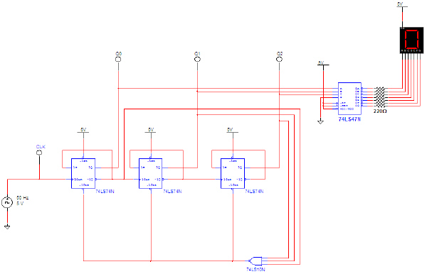
3-Bit Mod-6 Up Counter with D Flip-Flops
a. Use Multisim to enter the 3-Bit Mod-6 Up
Counter. Add a four-channel oscilloscope to monitor the signals Q0, Q1, Q2, and
the output of the NAND gate. Run the simulation and capture a full count cycle (0-5) of the signal.
Verify that the circuit is working as expected. If the results are not what are expected, review your
circuit and make any necessary corrections. SHOW ME YOUR WORKING
CIRCUIT!
b. Adjust the time-base of
the oscilloscope to zoom into the point in time that the counter is changing from a count of 5 (101)
to 0 (000). Show me your
waveforms.
c. Make the necessary
modification to this circuit to change the count to 2 (010) to 6 (110). This is now a Mod-7 Up
Counter with a start of 2 (010). Run the simulation and verify that the circuit is working as
expected. If not, review your circuit, make any necessary corrections, and retest. Use a 74LS48 and a
common cathode seven-segment display for this simulation in preparation for the next problem.
SHOW ME YOUR WORKING
CIRCUIT!