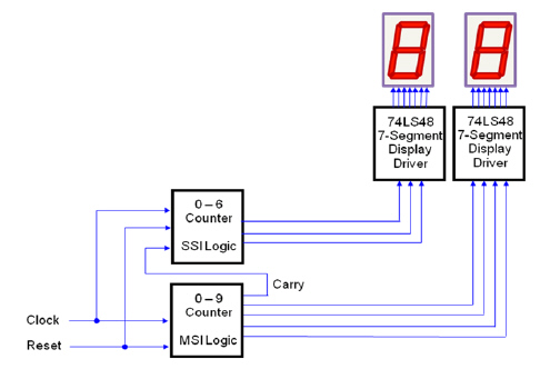
Design a digital Sixty
Second Timer that counts from 00 to 60. This design has two control inputs and two output displays.
The two inputs are Clock and
Reset. The Clock signal is a 1 Hz square wave that controls the count rate. The
Reset signal, when it is a logic zero, resets and holds the count at zero. When the
Reset signal is a logic one, counting is enabled. When the count reaches sixty seconds, the
counting ceases.
IC Chips:
74LS48
74LS93 74LC74
74LS76
Design Specifications:
· The two output displays are common cathode seven-segment displays.
· Current limiting
resistors (150 W - 270 W) must be used.
· Each display will use a
74LS48 BCD-To-Seven-Segment display driver.
· The ones-unit display
(0-9) is controlled by an asynchronous counter designed with a 74LS93 MSI counter IC.
· The tens-unit display
(0-6) is controlled by an asynchronous counter designed with SSI logic gates (D or
J/K).
· Any additional logic may be used as needed to support the counter
designs.
Simulation
Using Multisim, enter and test your Sixty Second Timer
design. Verify that the circuit is working as designed. If not, review your design work and circuit
implementation to identify your mistake. Make any necessary corrections and retest. Be sure to
document all changes in your engineering notebook. Show me your working
circuit!
Prototyping
Breadboard and test your Sixty Second Timer design. Verify that the circuit is
working as designed. If it is not, do not change your design. You know that your design is good
because you simulated it. If your circuit isn’t working correctly, you must have built
something incorrectly. Review your circuit implementation to identify your mistakes, make the
necessary corrections, and retest.
If time allows, we will program the FPGA board to simulate
the 60 second timer.