Name:     ID: 
 
Email: 

U3L2MSIAsynchronouscounters

Problem
 

 1. 


Manufactures of integrated circuits frequently take digital circuit designs, which are commonly implemented with SSI gates, and create equivalent Medium Scale Integrated (MSI) circuits. This is precisely what has occurred with the 74LS93 4-Bit Counter. 
In this activity we will simulate and analyze a 4-Bit 
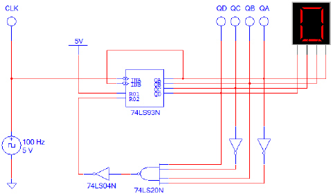
asynchronous counter using a 74LS93 4-Bit Counter.
      The circuit shown below is a 4-Bit Binary-Up Counter implemented with 74LS93 MSI Counter IC. This design will count from 0 to 9 and then repeat.

pr001-1.jpg
4-Bit Binary-Up Counter


a.      Using the Multisim, enter the 4-Bit Binary-Up Counter. Add a four-channel oscilloscope to monitor the signals QD, QC, QB, and QA. Run the simulation and capture a full count cycle (0-9) of the signal. Verify that the circuit is working as expected. If the results are not what are expected, review your circuit and make any necessary corrections. Show me your working circuit.

b.      Make the necessary modification to this circuit to change the count limit to ‘C’ (1100). Run the simulation and verify that the circuit is working as expected. If not, review your circuit, make any necessary corrections, and retest.  Show me your working circuit.
 

 2. 


      The circuit shown below is the same as the 0-9 4-Bit Binary-Up Counter implemented in step (1) with a few modifications. First, a single-pole-single-through switch (A) and a 2-input AND gate were added to the clock input. This modification provides a means for the count to be suspended. The second modification, the addition of a second SPST switch (B) and a 2-input NAND gate, provides a means to reset the count to zero.
pr002-1.jpg                        Modified 4-Bit Binary-Up Counter

a.      Using Multisim, enter the Modified 4-Bit Binary-Up Counter.

b.      With the switches (A) and (B) set to 5V, start the simulator. Verify that the circuit is working as expected. If the results are not what are expected, review your circuit and make any necessary corrections. You may need to adjust the simulation speed to observe the outputs changing. 
Show me your working circuit.

c.      With the simulation running, toggle the switch (A) switch to GROUND. What effect does this have on the output? Toggle switch (A) back to 5V. What effect does this have on the output?

d.      With the simulation running, toggle the switch (B) switch to GROUND. What effect does this have on the output? Toggle switch (B) back to 5V. What effect does this have on the output?

Answer c and d in the box below.


         Start Over