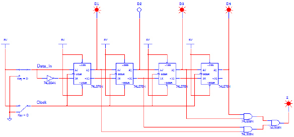
The circuit shown is a 4-bit shift register that is used
to detect the input sequence 1,1,0,1. When this input sequence is detected, the output Z will be on.
At all other times, the output Z will be off.
a. Using Multisim, create the 4-bit shift
register circuit.
b. Start the simulation and
verify that the circuit is working as expected by trying various input sequences and confirming that
the sequence 1,1,0,1 is detected while others are not. If the circuit is not working as expected,
review your circuit and make any necessary corrections. Show me your working circuit or email me a
copy if you did it at home.
c. Make the necessary modification to the
circuit so that it will detect the input sequence 0,1,1,0. Simulate this new circuit and verify that
it is working as designed. If not, make any necessary corrections. Show me your working circuit
or email me a copy if you did it at home.
Did your circuits in part b and part c work
correctly? Answer yes or no.