Multiple Choice
Identify the
choice that best completes the statement or answers the question.
|
|
|
1.
|
A demultiplexer is a device
which
a. | generates an encoded output from a
numeric input. | b. | routes a single data input onto one of several data
outputs. | c. | converts some code into a recognizable number or
character. | d. | selects one of several inputs to be placed onto one output
line. |
|
|
|
2.
|
A device which places its input
data onto one of several outputs is a
a. | comparator. | c. | multiplexer. | b. | counter. | d. | demultiplexer. |
|
|
|
3.
|
Why are LED displays often
multiplexed?
a. | to save
power | b. | so that multiplexers can be used | c. | because the data is not available for all displays at
once | d. | to save time |
|
|
|
4.
|
A multiplexer is also known as
a(n)
a. | code
converter. | c. | decoder. | b. | encoder. | d. | data selector. |
|
|
|
5.
|
An everyday illustration of a
multiplexer is
a. | the treble-bass control on a stereo
receiver. | b. | the balance control on a stereo receiver. | c. | the function switch on a stereo
receiver. | d. | the volume control in a stereo
receiver. |
|
|
|
6.
|
A multiplexer is a device
which
a. | selects one of several inputs to be
placed onto one output line. | b. | converts some code into a recognizable number or
character. | c. | routes a single data input onto one of several data
outputs. | d. | generates an encoded output from a numeric
input. |
|
Problem
|
|
|
7.
|
The schematic diagram shown below is designed to display
the word OPEN on four seven-segment displays. Though this design works, it is an inefficient use of
power. Each segment draws approximately 18 mAmps from a 5V power supply. Since Power = Voltage x
Current (P=VI), each segment is using 90 mWatts of power. Thus, to display the word OPEN, a total of
1.89 watts of power is required. This may not seem like much power, but consider all of the displays
that you see every day. If they were all designed using this technique, a tremendous amount of power
would be wasted.
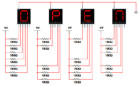
Using Multisim, enter
this circuit and verify that it is working as expected.
Show me your circuit in class. For
your answer, put “verified in class”.
|
|
|
8.
|
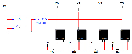
A significantly better way to display the word OPEN
would be to multiplex the seven-segment displays. Thus, for the word OPEN to be displayed properly,
the displays must be de-multiplexed. The schematic diagram shown below accomplishes this task by
using a 74LS139 2-to-4 de-multiplexer and 2 switches. (In a real application, a counter would
replace the switches. Counters will be discussed in Unit 3.) In this implementation only one display
is on at any given time, resulting in significantly reduced power usage.
Use Multisim to create this circuit and verify that the circuit is
working as expected. Show me your working circuit and your completed truth table. In your
answer, write “verified in class”.
B | A | Y0 | Y1 | Y2 | Y3 | 1st
Display | 2nd
Display | 3rd
Display | 4th
Display | 0 | 0 | | | | | | | | | 0 | 1 | | | | | | | | | 1 | 0 | | | | | | | | | 1 | 1 | | | | | | | | | | | | | | | | | | |
|
|
|
9.
|
Use the knowledge gained from implementing the
multiplexed version of the circuit that displayed the word OPEN to design a circuit that displays the
word HELP. Use Multisim to create
this circuit and verify that the circuit is working as expected. Show me your working circuit
and your completed truth table. In your answer, write “verified in
class”.
B | A | Y0 | Y1 | Y2 | Y3 | 1st
Display | 2nd
Display | 3rd
Display | 4th
Display | 0 | 0 | | | | | | | | | 0 | 1 | | | | | | | | | 1 | 0 | | | | | | | | | 1 | 1 | | | | | | | | | | | | | | | | | | |
|
|
|
10.
|
The circuit shown below takes the simplification of the circuit that
displays the word OPEN to the next level. This circuit uses the same amount of power as the original
multiplexed circuit but requires fewer (and differently-sized . . . HINT) resistors.
Explain how this circuit works.
|