Name:     ID: 
 
Email: 

U2L3SevenSegmentDisplays

Problem
 

 1. 


a.      Using the Multisim, enter the seven-segment display test circuit shown below. Please note that the seven-segment display is a common cathode display.
                                    pr001-1.jpg

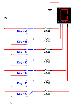
b.      For the seven switches (i.e., A thru G), determine the settings required so that the seven-segment display will display 0-9. Use the results to complete the table shown below.

Display
a
b
c
d
e
f
g
0
1
1
1
1
1
1
0
1
       
2
       
3
       
4
       
5
       
6
       
7
       
8
       
9
       

c.      Again, using the seven SPDT switches (i.e., A thru G), determine at least ten alpha characters that you could display using the seven-segment display. Don’t forget to include lower case characters. Record your findings in the table shown below.
 

 2. 


a.      Analyze the seven-segment display circuit shown below and complete the display table shown. The display is a common cathode.


b.      What message do you predict will be displayed?


pr002-1.jpg

J
K
Display
0
0
 
0
1
 
1
0
 
1
1
 
c.      Using a breadboard, build and test the seven-segment circuit that you analyzed and simulated. Limit your implementation to only 2-input OR gates (74LS32), inverters (74LS04), and a common cathode seven-segment display. DON’T FORGET THE 220 W RESISTORS.
 

 3. 


      Complete the wiring of the seven-segment displays shown below so that they will display your age. If you are 15, display a (1) on the common cathode display and a (5) on the common anode display.  Show me yours in class once you have completed it.
pr003-1.jpg


         Start Over