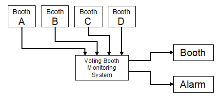
The block diagram below represents a voting booth monitoring system. For
privacy reasons, a voting booth can only be used if the booth on either side is unoccupied. The
monitoring system has four inputs and two outputs. Whenever a voting booth is occupied, the
corresponding input (A,B,C, &d) is a (1). The first output, Booth is a (!) whenever the
voting booth is available. The second output, Alarm, is a (1) whenever the privacy rule is
violated.
Implement NAND only combinational
logic circuits for the two outputs
Booth and
Alarm. These NAND only designs will
be compared with the original AOI implementations in terms of efficiency and gate/IC
utilization.
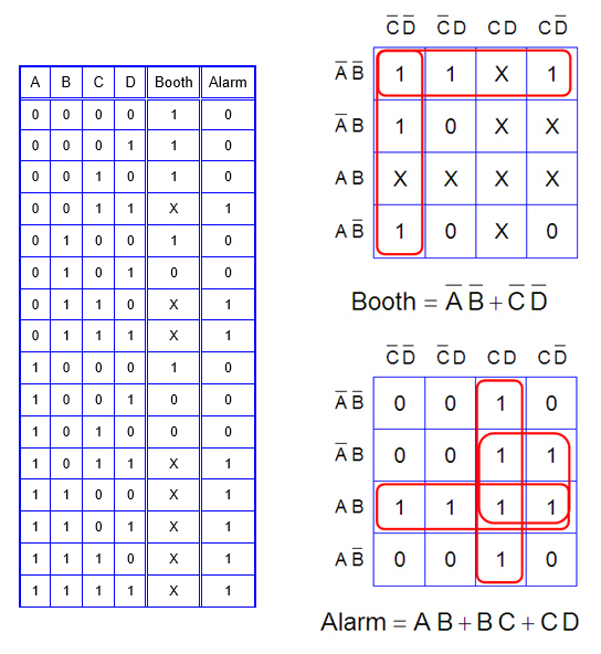
For the sake of time, the truth table and K-Maps for the voting booth
monitor systems have been completed for you. Note, the output for
Booth utilized several
don’t care conditions.
Part 1:
Using Multisim, draw the AOI
circuits that implement the simplified logic expressions,
Booth and
Alarm. Limit
this implementation to only 2-input AND gates (74LS08), s-input OR gates (74LS32), and inverrters
(74LS04).
Part 2:
Re-implement these circuits assuming that only 2-input NAND gates
(74LS00) are available. Using Multisim, draw these circuits.
Booth
NAND
Alarm NAND
Part 3:
Draw the
Booth NAND and
Alarm NAND as one
circuit.
Use switches for the inputs A, B, C, and D and a probe or LED for the outputs
Booth and
Alarm. Verify that the circuits are working as expected.
Email me a
copy of your circuits from Part 1 and Part 2. I must verify that your simulation is working in
class.