Now that you are all
experts at logic simplification using Boolean algebra and K-Mapping and can implement virtually any
combinational design using AOI, NAND, and NOR gates, it’s time to let you in on a little
secret. A tool located within the Multisim Circuit Design Software, called the Logic Converter, can do much of this work for you.
You might be asking yourself why you weren’t given this tool sooner. As an engineer you
need to know how to design these types of circuits with and without the aid of such tools. Besides,
who do you think designs tools like the Logic Converter? That’s right, an engineer.
In
this activity you will complete a brief tutorial and use the Logic Converter to create and simulate
both an AOI and NAND circuit design.
MultiSim’s Logic Converter is not a real-world
component, but is a virtual tool that can be used to produce a logic circuit from an entered truth
table or logic expression.
Though you will not be using it in this activity, the
Logic Converter can also be attached to a circuit to derive its equivalent truth table and
logic expression.
The layout of the Logic Converter’s interface panel is shown
below.
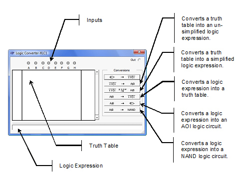
Complete the following steps to learn the
capabilities of the Logic Converter.
1. Start MultiSim and click
on the Logic Converter button in the instrument toolbar. Place the icon in the workspace and
double-click the icon to open the instrument interface panel.
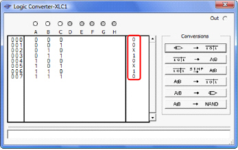
2. In
the Inputs section of
the Logic Converter, select input A, B, and C.
3. In the Truth Table area of Logic
Converter, enter the truth table as shown below.
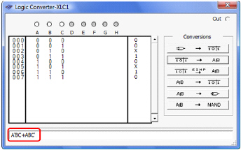
4. To generate the un-simplified logic expression, select
the  button. The logic expression will be displayed
in the Logic Expression area of the Logic Converter as shown
below.
button. The logic expression will be displayed
in the Logic Expression area of the Logic Converter as shown
below.
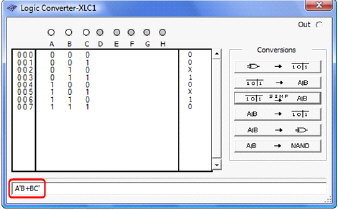
5. To generate the simplified logic expression, select
the  button. The logic expression will be displayed
in the Logic Expression area of the Logic Converter as shown
below.
button. The logic expression will be displayed
in the Logic Expression area of the Logic Converter as shown
below.
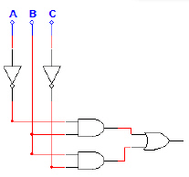
6. To generate the AOI logic circuit for this logic
expression, select the  button. The AOI logic circuit will be added to
the drawing area of MultiSim as shown below.
button. The AOI logic circuit will be added to
the drawing area of MultiSim as shown below.
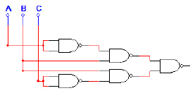
7. To generate the NAND logic circuit for this logic
expression, select the  button. The NAND logic circuit will be added
to the drawing area of MultiSim as shown
below.
button. The NAND logic circuit will be added
to the drawing area of MultiSim as shown
below.
The truth table shown below is for the Majority Vote – Voting Machine project that
you completed in the previous lesson. Let’s use the Logic Converter to create an AOI and NAND
only logic circuit for this project.
P | V | S | T | Vote |
0 | 0 | 0 | 0 | 0 |
0 | 0 | 0 | 1 | 0 |
0 | 0 | 1 | 0 | 0 |
0 | 0 | 1 | 1 | 0 |
0 | 1 | 0 | 0 | 0 |
0 | 1 | 0 | 1 | 0 |
0 | 1 | 1 | 0 | 0 |
0 | 1 | 1 | 1 | 1 |
1 | 0 | 0 | 0 | 0 |
1 | 0 | 0 | 1 | 1 |
1 | 0 | 1 | 0 | 1 |
1 | 0 | 1 | 1 | 1 |
1 | 1 | 0 | 0 | 1 |
1 | 1 | 0 | 1 | 1 |
1 | 1 | 1 | 0 | 1 |
1 | 1 | 1 | 1 | 1 |
| | | | |
1. Enter the truth table for the
Majority Vote – Voting
Machine into the Logic Converter. Unfortunately, you can’t change the variable names in the
Logic Converter, so variables P, V, S, and T will be represented
by A, B, C, and D.
2. Use the Logic Converter
to first generate, and then simplify the logic expression for the output Vote.
3. Use the Logic Converter
to create the AOI logic implementation of the Majority Vote – Voting Machine. Use switches for the inputs A, B, C,
and D (which you should now rename P, V, S, and
T) and a probe or LED circuit for the output Vote. Verify that
the circuit is working as expected. Print a copy of the
circuit.
4. Use the Logic Converter to create the NAND Only
logic implementation of the Majority Vote – Voting Machine. Use switches for the inputs
A, B, C, and D (again, you should rename them P, V, S,
and T) and a probe or LED circuit for the output
Vote. Verify that the circuit is working as expected. Print a copy of the
circuit.
5. How did the AOI implementation of the
Majority Vote –
Voting Machine created
by the Logic Converter compare to the design that you completed manually in the previous
lesson?