The Acme Fireplace Company has hired you to redesign the fireplace control
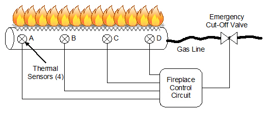
circuit for their latest residential gas fireplace. The fireplace burner is equipped with four
thermal sensors that output a logic (1) whenever a flame is present. These sensors are connected to
the fireplace control circuit which outputs a (1) to the emergency cut-off valve to keep the gas
flowing (i.e., a zero will turn the gas off).
The original design of the fireplace control
circuit was quite simple. For the gas valve to remain on, all four sensors needed to output a logic
(1). During field testing it was discovered that variations in gas pressure and humidity cause the
thermal sensors to occasionally output a logic (0) even when a flame is present. This caused frequent
unnecessary shut downs and constant customer dissatisfaction.
For the
redesign, is has been determined that the emergency cut-off value should remain open as long as three
of the four sensors indicate that a flame is present.
Additionally, the designers have asked
you to add a second output indicator to the control circuit. This indicator will output a logic (1)
when the four sensors do not all agree (i.e., not all on, or not all off). This indicator will be
used by the service technician to diagnose whether a faulty sensor
exists.
Procedure
Design
Design a combinational logic circuit that meets the above
detailed design specifications.
Additionally:
· The Karnaugh mapping
technique must be used to obtain the simplified logic expression for both outputs.
· The circuit that
controls the emergency cutt-off valve must be implemented using only 74LS00 two-input NAND
gates.
· The circuit for the possible faulty sensor indicator must
be implemented using only 74LS02 two-input NOR gates.
Simulation
Using Multisim, enter and test your Fireplace Control
Circuit design. Use switches for the inputs A, B, C, and D and a
probe or LED circuit for the two outputs. Verify that the circuit is working as designed. If it is
not, review your design work and circuit implementation to identify your mistake. Make any necessary
corrections and retest.
Write a conclusion (minimum 250 words) that describes the process that you
used to design, simulate, and build your Fireplace Control Circuit. This conclusion must include all of your design work
(i.e., truth table, K-Maps, etc.), preliminary and final schematics, parts list, and a digital
photograph of your final circuit. The documentation should be complete enough that a student with a
similar knowledge of digital electronics could reproduce your design without any additional
assistance.