Multiple Choice
Identify the
choice that best completes the statement or answers the question.
|
|
|
1.
|
When a flip-flop is RESET,
________.
a. | Q = 1,  =
0 =
0 | c. | Q = 0,  =
0 =
0 | b. | Q = 0,  =
1 =
1 | d. | Q =  |
|
|
|
2.
|
When a flip-flop is SET,
________.
a. | Q and  =
1 =
1 | c. | Q =
0 | b. |  =
1 =
1 | d. | Q = 1,  =
0 =
0 |
|
|
|
3.
|
An edge-triggered flip-flop can
only change states when
a. | the D input is
HIGH. | c. | the trigger input changes
levels. | b. | the trigger is HIGH. | d. | the trigger is LOW. |
|
|
|
4.
|
Which of the following
flip-flops have synchronous inputs?
a. | 7474
D-flip-flop | c. | S-R
flip-flop | b. | NAND flip-flop | d. | all of the above |
|
|
|
5.
|
A positive edge-triggered
flip-flop will only accept inputs when the clock
a. | is
HIGH. | c. | is
LOW. | b. | changes from LOW to HIGH. | d. | changes from HIGH to LOW. |
|
|
|
6.
|
A negative edge-triggered
flip-flop will only accept inputs when the clock
a. | is
HIGH. | c. | changes from LOW to
HIGH. | b. | is LOW. | d. | changes from HIGH to LOW. |
|
Problem
|
|
|
7.
|
Using Multisim, enter the D flip-flop test
circuit shown below. Use a switch for the input T and probes for the outputs Que and
NOT_Que.
Note: The PR (preset) and CLR (clear) inputs on the 74LS74
are active low inputs. In this circuit PR and CLR are connected to 5v (high), which makes them both
inactive.
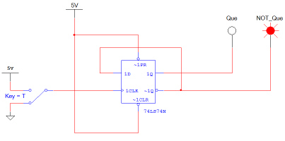
Toggle the input T several times and
record what effect this has on the two outputs.
What happens
when the switch is moved from GROUND to 5v? What happens
when the switch is moved from 5v to GROUND? Explain.
|
|
|
8.
|
Using Multisim, modify the circuit used in problem 1 so
that it matches the example shown below.
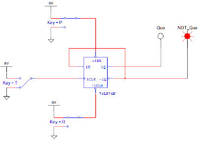
Start the simulation.
Set the input switches P and R
to 5v. Again, since PR and CLR are active low inputs, this will make them both inactive.
Toggle the input T several times. The circuit should behave exactly like the circuit in
problem 1.
A) Set the input switch P to GROUND
and R to 5v. What is the state of the two outputs?
B) Toggle the input T several times and record what effect this has
on the two outputs. Set the input switch P to 5v and R to
GROUND. What is the state of the two outputs?
C) Toggle the input T several times and record what effect this has on the
two outputs.
|
|
|
9.
|
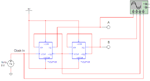
Let us examine a simple
binary counter. Counters are one of the most common applications of flip-flops. The circuit that we
will be observing is called a two-bit binary counter. The counter will count from zero (00 in binary)
to three (11 in binary).
Using the Multisim, enter
the two-bit binary counter shown below. Use a switch for the input Clock-In and probes
for the outputs A and B.

Start the
simulation
Cycle the input Clock-In (switch T)
several times and record what effect this has on the two outputs in the table below. Make
your table on a separate sheet of paper.
Clock-In | A | B | Initial Values | | | 1st Toggle | | | 2nd
Toggle | | | 3rd Toggle | | | 4th
Toggle | | | 5th Toggle | | | 6th
Toggle | | | | | |
Based on these results, explain the pattern
that you observe in the two outputs.
|
|
|
10.
|
Using Multisim, modify the circuit used in step
(1) so that it matches that shown below.
The first modification
is to replace the switch input with a CLOCK_VOLTAGE. This change will result in the input
being continuously toggled. Be sure the CLOCK_VOLTAGE is set to 5 volts, 50% duty cycle, 1 kHz.
The second modification is to add a four-channel oscilloscope set up to view the four signals
A, B, Clock-In, and ~1Q (i.e., the Q-not
output of the first flip-flop). Be sure to set the oscilloscope’s time-base to 1ms/div and the
vertical-bases of the four channels to 10volts/div. Also, adjust the Y position of the four channels
such that the four signals are all clearly visible.
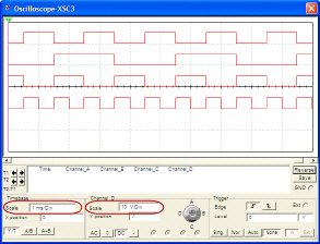
a) Start the simulation and let it run until you
have captured several periods of each signal.
a) Using the
oscilloscope’s markers, measure the period of the three signals. Use this data to calculate the
frequency for each signal. Record your data in the table below. Be sure to use the correct
units.
Signal | Period | Frequency | Clock-In | | | A | | | B | | | | | | | | | |
Based on these results,
explain the relationship of the period and frequency between the three signals. Was this
expected?
List 3-5
real-world applications where you might find counters like
the one examined in this activity.
|
|
|
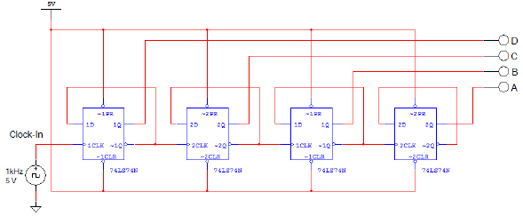
11.
|
Analyze the 4-bit binary
counter shown below to determine the frequency and period for the signals A, B, C, and D. Use the
table shown below to record your answers.
Signal | Period | Frequency | Clock-In | | | A | | | B | | | C | | | D | | | | | |
|