Now that the combinational logic section is working
(problem 1), let’s construct and simulate it the sequential logic section. Using Multisim,
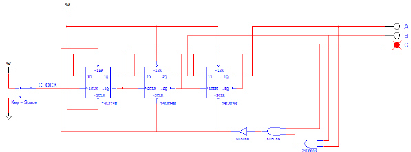
enter the sequential logic section of the Board Game Counter shown below. For the initial analysis,
we will use a switch to generate the signal CLOCK.
 Sequential Logic Section – Board
Game Counter
Sequential Logic Section – Board
Game Counter
a) Start the
simulation.
b) Cycle the input
CLOCK several times and
record the value of the outputs A, B, and C in the table
shown below.
CLOCK | A | B | C |
Initial
Values | 0 | 0 | 1 |
1st
Toggle | | | |
2nd Toggle | | | |
3rd Toggle | | | |
4th Toggle | | | |
5th Toggle | | | |
6st Toggle | | | |
7th Toggle | | | |
| | | |
c) Is the counter counting
as expected (see below)? If not, check your circuit to make sure that it was built correctly. Make
any necessary corrections and repeat steps (a) and (b).
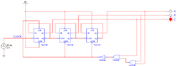
d) Modify the circuit by replacing the input switch with
a CLOCK_VOLTAGE set to 5 volts, 50% duty cycle @ 50 Hz (see below). The CLOCK_VOLTAGE will
continuously toggle the input, causing the output to repeatedly cycle through the count 001 to
110.
 Sequential Logic Section – Board
Game Counter
Sequential Logic Section – Board
Game Counter
a) Start the simulation.
b) Observe the outputs A, B, and
C. They should be cycling through the following pattern:
c) Is the counter counting as expected? If not,
check your circuit to make sure that it was built correctly. Make any necessary corrections and
repeat steps (e) and (f).
Note: Do this assignment on paper, you won’t be able to
enter in all of the data into the given space on this problem.