Yes/No
Indicate whether you
agree with the statement.
|
|
|
1.
|
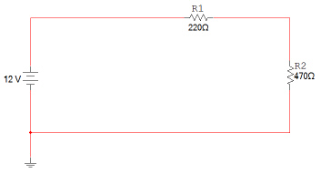
Shown below is the schematic for a simple series
circuit. Analyze this circuit to determine its total current and the voltage across each of the two
resistors. To make these measurements, add an ammeter and two voltmeters. The second schematic shown
is the original circuit with the added meters.
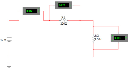
Using the Multisim, enter and simulate this circuit. Measure and record the
circuit’s total current and the voltage across each of the resistors. Verfiy your circuit
using KVL.
Show me your working circuit before you answer this question.
Do your hand
calculations match your simulated calculations?
|
|
|
2.
|
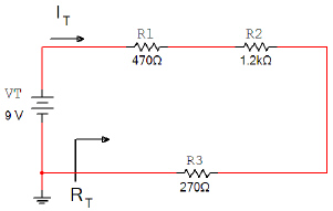
Using the Multisim, analyze the circuit shown
below to determine IT,
VR1, VR2, & VR3. Add the appropriate ammeters and voltmeters. Be
sure to put your answer in proper engineering notation and use the correct
units.
 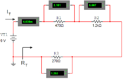 Using the Multisim, enter and simulate this circuit. Measure and record the
circuit’s total current and the voltage across each of the resistors. Verfiy your circuit using
KVL.
Show me your working circuit before you answer this
question.
Do your hand calculations match your simulated
calculations?
|
|
|
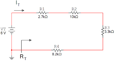
3.
|
Using the Multisim, analyze the circuit shown below to
determine IT, VR1, VR2, VR3, & VR4.
Add the appropriate ammeters and voltmeters. Be sure to put your answer in
proper engineering notation and use the correct units.
 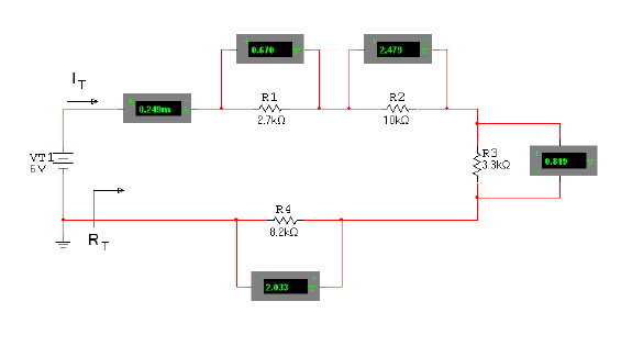 Using the Multisim, enter
and simulate this circuit. Measure and record the circuit’s total current and the voltage
across each of the resistors. Verfiy your circuit using KVL.
Show me your working circuit
before you answer this question.
Do your hand calculations match your simulated
calculations?
|
|
|
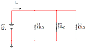
4.
|
Using the Multisim, analyze the circuit shown below to
determine IT, IR1, IR2, & IR3. Add the appropriate ammeters and voltmeters. Be sure to put your answer in proper
engineering notation and use the correct units.
 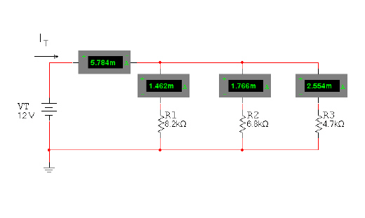 Using the Multisim, enter
and simulate this circuit. Measure and record the circuit’s total current and the voltage
across each of the resistors. Verfiy your circuit using KCL.
Show me your working circuit
before you answer this question.
Do your hand calculations match your simulated
calculations?
|
|
|
5.
|
Using the Multisim, analyze the circuit shown below to
determine IT, IR1, IR2, IR3, &
IR4. Add the appropriate ammeters and voltmeters. Be sure to put your
answer in proper engineering notation and use the correct units.
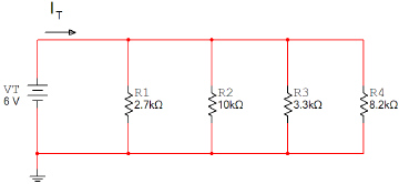 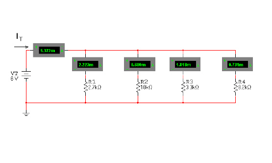 Using the Multisim, enter
and simulate this circuit. Measure and record the circuit’s total current and the voltage
across each of the resistors. Verfiy your circuit using KCL.
Show me your working circuit before
you answer this question.
Do your hand calculations match your simulated
calculations?
|