Multiple Choice
Identify the
choice that best completes the statement or answers the question.
|
|
|
1.
|
When measuring voltage drop across a specific resister in a series circuit with
a DMM, the DMM must be placed in ___________ with the resister to read the voltage drop.
a. | series | c. | neither series or parallel | b. | parallel |
|
|
|
2.
|
When measuring current in a series circuit with a DMM, the DMM must be placed in
___________ with the circuit to read the current.
a. | series | c. | neither series or parallel | b. | parallel |
|
|
|
3.
|
When measuring voltage in a parallel circuit with a DMM, the DMM must be placed
in ___________ with the resister to read the voltage drop.
a. | series | c. | neither series or parallel | b. | parallel |
|
|
|
4.
|
When measuring current in a parallel circuit with a DMM, the DMM must be placed
in ___________ with each resistor individually to read the individual branch currents.
a. | series | c. | neither series or parallel | b. | parallel |
|
Completion
Complete each
statement.
|
|
|
5.
|
Using a Bread Board
and variable power supply, construct the circuit shown below. Use a digital multimeter to measure
IT, VR1, VR2, & VR3.
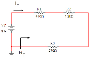
Remember, unlike measuring voltage, the current measurement is an intrusive
measurement. This means that you must temporarily modify the circuit. Redirect the current through
the DMM and then direct it back to the circuit.
In this activity you will alternately measure
voltage and current with the same DMM. Be sure that the meter is in the proper mode for what is being
measured before the power is applied.
This circuit was analyzed by hand in your circuit theory
assignment and simulated in your circuit theory using multisim assignment. How do these measured
values compare to the previously calculated and simulated values? If they do not match, review your
circuit, your calculations, and make any necessary corrections.
|
|
|
6.
|
Using a Bread Board
and variable power supply, construct the circuit shown below. Use a digital multimeter to measure
IT, VR1, VR2, VR3, & VR4.
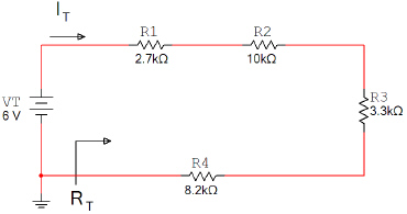
Remember, unlike measuring voltage, the current measurement is an intrusive
measurement. This means that you must temporarily modify the circuit. Redirect the current through
the DMM and then direct it back to the circuit.
In this activity you will alternately measure
voltage and current with the same DMM. Be sure that the meter is in the proper mode for what is being
measured before the power is applied.
This circuit was analyzed by hand in your circuit theory
assignment and simulated in your circuit theory using multisim assignment. How do these measured
values compare to the previously calculated and simulated values? If they do not match, review your
circuit, your calculations, and make any necessary corrections.
|
|
|
7.
|
Using a Bread Board
and variable power supply, construct the circuit shown below. Use a digital multimeter to measure
IT, IR1, IR2, & IR3.
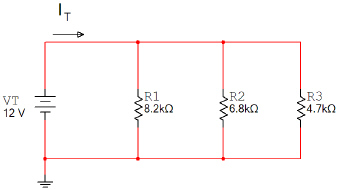
Remember, unlike measuring voltage, the current measurement is an intrusive
measurement. This means that you must temporarily modify the circuit. Redirect the current through
the DMM and then direct it back to the circuit.
In this activity you will alternately measure
voltage and current with the same DMM. Be sure that the meter is in the proper mode for what is being
measured before the power is applied.
This circuit was analyzed by hand in your circuit theory
assignment and simulated in your circuit theory using multisim assignment. How do these measured
values compare to the previously calculated and simulated values? If they do not match, review your
circuit, your calculations, and make any necessary corrections.
|
|
|
8.
|
Using a Bread Board
and variable power supply, construct the circuit shown below. Use a digital multimeter to measure
IT, IR1, IR2, IR3, & IR4.
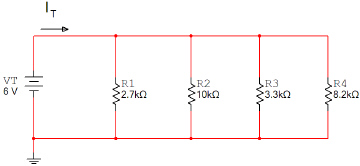
Remember, unlike measuring voltage, the current measurement is an intrusive
measurement. This means that you must temporarily modify the circuit. Redirect the current through
the DMM and then direct it back to the circuit.
In this activity you will alternately measure
voltage and current with the same DMM. Be sure that the meter is in the proper mode for what is being
measured before the power is applied.
This circuit was analyzed by hand in your circuit theory
assignment and simulated in your circuit theory using multisim assignment. How do these measured
values compare to the previously calculated and simulated values? If they do not match, review your
circuit, your calculations, and make any necessary corrections.
|