Shown below is the analog
section of the Board Game Counter.
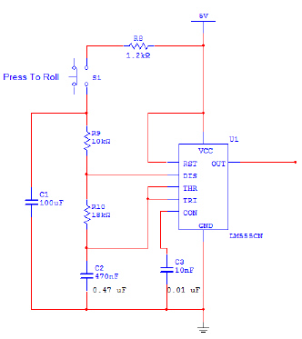
Analog Section – Board Game Counter
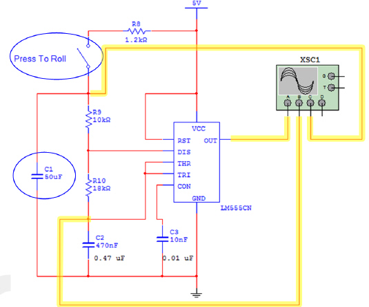
Unfortunately, there are
two issues with simulating this circuit as shown. First, it is difficult to obtain accurate
simulation results using the push button switch (S1). Additionally, the 100 mf capacitor (C1) causes the simulation to run too
long.
To fix these issues, we must make two simple changes to the circuit. First,
replace the push button switch with an SPST switch. Change the 100 mf capacitor to 50 mf. These changes are shown below. Also shown are the oscilloscope connections
(highlighted).
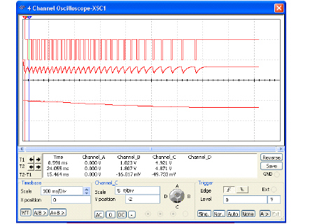
1. Using the Circuit Design Software (CDS),
enter the modified analog section of the Board Game Counter shown.
2. With the switch closed, start the
simulation.
3. Open the oscilloscope tool and adjust the scale of
the timebase and channels so that the three signals are easy to see and measure (see below).
4. Restart the
simulation.
5. After the first few square waves are observed on the
output signal, open the switch. Let the simulation run until the output signal stops oscillating.
When the oscillation stops, stop the simulation. This may take a few
minutes.
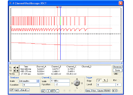
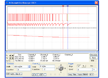
6. Adjust the oscilloscope to display the first square wave
of the output signal. Using the oscilloscope’s markers, measure the period of this signal. Use
this data to calculate the frequency. Record your result in the table.
Signal | Period | Frequency |
| First Square
Wave | 15.5ms | 64.5Hz |
| Middle
Square Wave | 27.5ms | 36.4Hz |
| Last
Square Wave | 51.6ms | 19.4Hz |
| | |
Note: Period results will vary depending on the wave that an
individual considers to be the middle wave. First and Last Wave
results may vary
slightly.
Repeat step 6 for a signal in the middle of the
simulation, approximately half way between the first and last square wave
observed.
Repeat step (6) for the last square wave observed prior to
the oscillation stop
point.
Answer the
following questions and email them to me.
1. When you press the push button of the Board
Game Counter, the 555 Timer oscillates at approximately 65 Hz. It you want the oscillation to start
at 100Hz, what value would you apply to C2?
2. The values of R8 & C1
determine the time from when the push button is released to when the oscillation stops. If you wanted
to lengthen this time period, what changes would you make to one or both of these components?
Explain.