Multiple Choice
Identify the
choice that best completes the statement or answers the question.
|
|
|
1.
|
What is the peak amplitude of the given signal? 
|
|
|
2.
|
What is the peak-to-peak amplitude of the given signal? 
|
|
|
3.
|
What is the period of the given signal?  a. | 200ns | c. | 500ns | b. | 2000ns | d. | 400ns |
|
|
|
4.
|
What is the frequency of the given signal? 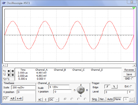 a. | 200Hz | c. | 5Hz | b. | 0.002Hz | d. | 2MHz |
|
|
|
5.
|
What is the peak amplitude of the given signal? 
|
|
|
6.
|
What is the peak-to-peak amplitude of the given signal? 
|
|
|
7.
|
What is the period of the given signal? 
|
|
|
8.
|
What is the frequency of the given signal? 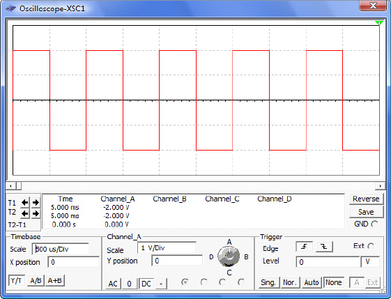 a. | 0.001Hz | c. | 2kHz | b. | 1kHz | d. | 10kHz |
|
|
|
9.
|
This signal is a __________ signal.  a. | Digital | c. | Analog | b. | Discrete | d. | random |
|
|
|
10.
|
This signal is a __________ signal.  a. | Digital | c. | Analog | b. | Discrete | d. | random |
|
|
|
11.
|
This signal is a __________ signal. 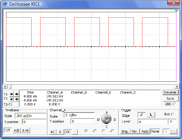 a. | Digital | c. | Analog | b. | Discrete | d. | random |
|
|
|
12.
|
What is the amplitude of the given signal? 
|
|
|
13.
|
What is the period of the given signal? 
|
|
|
14.
|
What is the time high of the given signal? 
|
|
|
15.
|
What is the time low of the given signal? 
|
|
|
16.
|
What is the frequency of the given signal?  a. | 2.5kHz | c. | 10kHz | b. | 5kHz | d. | 3.3kHz |
|
|
|
17.
|
What is the duty cycle of the given signal? 
|
|
|
18.
|
What is the amplitude of the given signal? 
|
|
|
19.
|
What is the period of the given signal?  a. | 1.65ms | c. | 1.5ms | b. |  | d. |  |
|
|
|
20.
|
What is the time high of the given signal?  a. | 1.65ms | c. | 1.5ms | b. |  | d. |  |
|
|
|
21.
|
What is the time low of the given signal?  a. | 1.65ms | c. | 1.5ms | b. |  | d. |  |
|
|
|
22.
|
What is the frequency of the given signal?  a. | 667Hz | c. | 6.6kHz | b. | 500Hz | d. | 606.06Hz |
|
|
|
23.
|
What is the duty cycle of the given signal? 
|
|
|
24.
|
What does “A” represent on the given waveform? 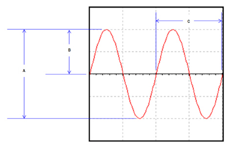 a. | Period | c. | Peak-to-Peak Amplitude | b. | Peak
Amplitude | d. | Frequency |
|
|
|
25.
|
What does “B” represent on the given waveform?  a. | Period | c. | Peak-to-Peak Amplitude | b. | Peak
Amplitude | d. | Frequency |
|
|
|
26.
|
What does “C” represent on the given waveform?  a. | Period | c. | Peak-to-Peak Amplitude | b. | Peak
Amplitude | d. | Frequency |
|
|
|
27.
|
What does “E” represent on the given waveform?  a. | Amplitude | c. | Time Low | b. | Time High | d. | Rising Edge |
|
|
|
28.
|
What does “F” represent on the given waveform? 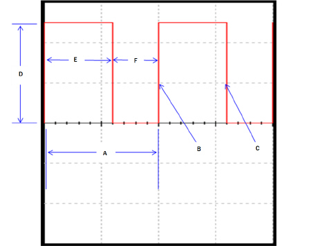 a. | Amplitude | c. | Time Low | b. | Time High | d. | Rising Edge |
|
|
|
29.
|
What does “D” represent on the given waveform?  a. | Amplitude | c. | Time Low | b. | Time High | d. | Rising Edge |
|
|
|
30.
|
What does “B” represent on the given waveform?  a. | Time Low | c. | Falling Edge | b. | Time High | d. | Rising Edge |
|
|
|
31.
|
What does “C” represent on the given waveform?  a. | Time Low | c. | Falling Edge | b. | Time High | d. | Rising Edge |
|
|
|
32.
|
What does “A” represent on the given waveform?  a. | Period | c. | Falling Edge | b. | Time High | d. | Rising Edge |
|
Multiple Response
Identify one
or more choices that best complete the statement or answer the question.
|
|
|
33.
|
Using the Circuit Design Software (CDS)
Multisim, enter the test circuit shown below. This circuit consists of a CLOCK_VOLTAGE, a DC_POWER
(battery) and two 5v LAMPS. This circuit doesn’t really do much of anything useful other than
make the two lamps flash, but we will be using it to gain experience using the oscilloscope to
measure signals.
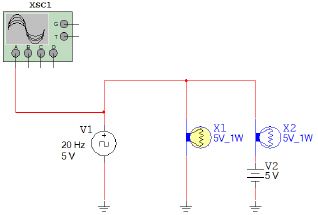
a) Open the CLOCK_VOLTAGE
component by double clicking on it and set the frequency, duty cycle, and voltage to 20 Hz, 10%, and
5 volts.
b) Likewise, open the DC_POWER and set the
voltage to 5 volts.
c) Finally, connect the OSCILLOSCOPE to
the positive side of the CLOCK_VOLTAGE component.
Start the simulation. Are the lamps flashing? Does the
flashing rate make sense for the frequency and duty cycle of the CLOCK_VOLTAGE? If not, review your
setup and make any necessary corrections. YOU MUST SHOW ME YOUR WORKING CIRCUIT.
Now
that the circuit is working, use the oscilloscope to measure the signal being generated by the
CLOCK_VOLTAGE. Use the markers to measure the period, time high, and time low. Use this data to
calculate the frequency and duty cycle of the signal. The markers are flags marked “1” and
“2” in the figure above. These can be dragged from side-to-side and lined up on the
vertical transitions of the wave. The readings for these markers are found in the area to the
right of the labels T1 and T2. In the figure below, Marker 1 is showing the Time High to be
about 5ms. Marker 2 is showing the period to be about 50ms.
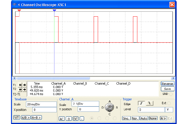
Calculate the duty cycle and
frequency.
|
|
|
34.
|
What are the two standard voltage levels that are acceptable for a digital
signal?
(Select two answers)
|